This post and the next three to follow will examine the life cycle test results of the four most common battery chemistries in use today; a sealed lead acid, a nickel metal hydride, a nickel cadmium and a lithium-ion polymer; using a PCBA 5010-4 battery analyzer to perform 1,000 charge/discharge cycles at the C/2 rate. The two-hour discharge rate was chosen to keep the discharge stress fairly low while still providing a brisk pace for achieving a thousand cycles in a reasonable amount of time. The C/2 discharge rate is admittedly fast for a lead acid battery whose capacity is typically rated by the manufacturer at the C/20 rate, this will result in a lower discharge capacity level for the lead acid type, but the idea of this life cycle testing with different chemistries is simply to compare the relative performance of the four most common chemistry types in order to gain a general appreciation for their capabilities and differences.
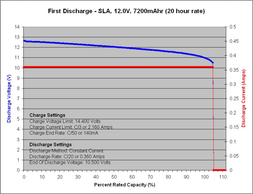
Figure 1 – Initial capacity test at C/20 rate
 The first sample to finish cycling 1,000 cycles was the 12V, 7.2Ah, VRLA battery from Panasonic, model LC-R127R2P1. Prior to the start of life cycle testing, the new battery was tested at the C/20 rate to ensure that it meets its 7,200 mAh rated capacity, and it did, by achieving 7,555mAh or 105%.
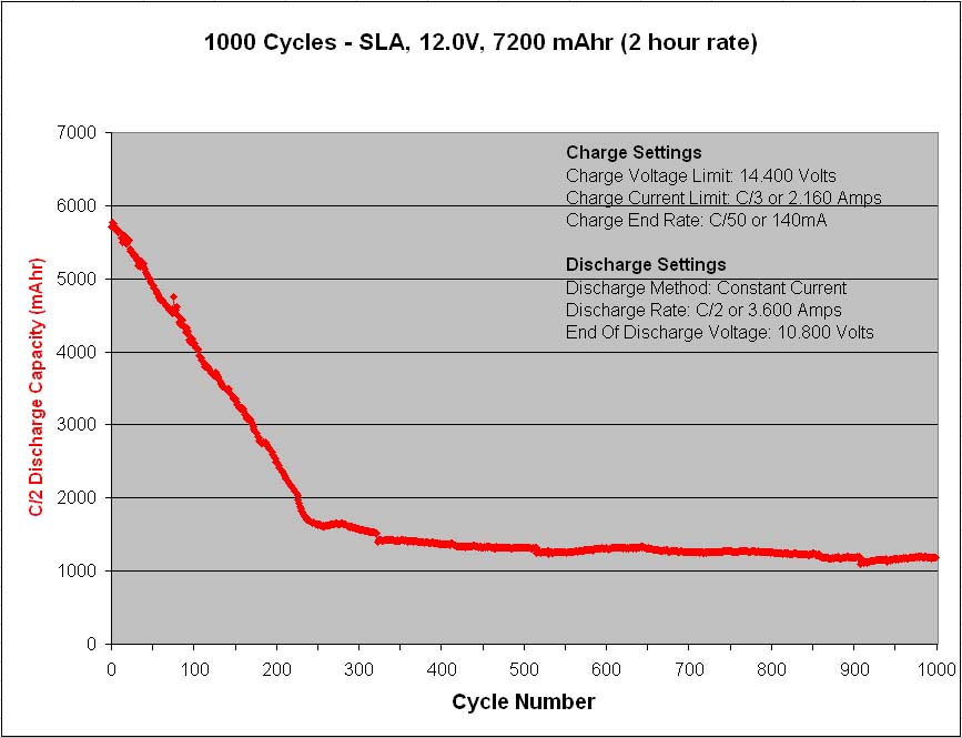
Figure 2 – Life cycle test results at C/2 rate
 At the C/2 discharge rate the capacity immediately drops to 5,700mAh and then steadily declines until reaching 1,650mAh after only 250 cycles, after which time the rapid capacity loss slows and the capacity averages near 1,300mAh for the remaining 750 cycles.
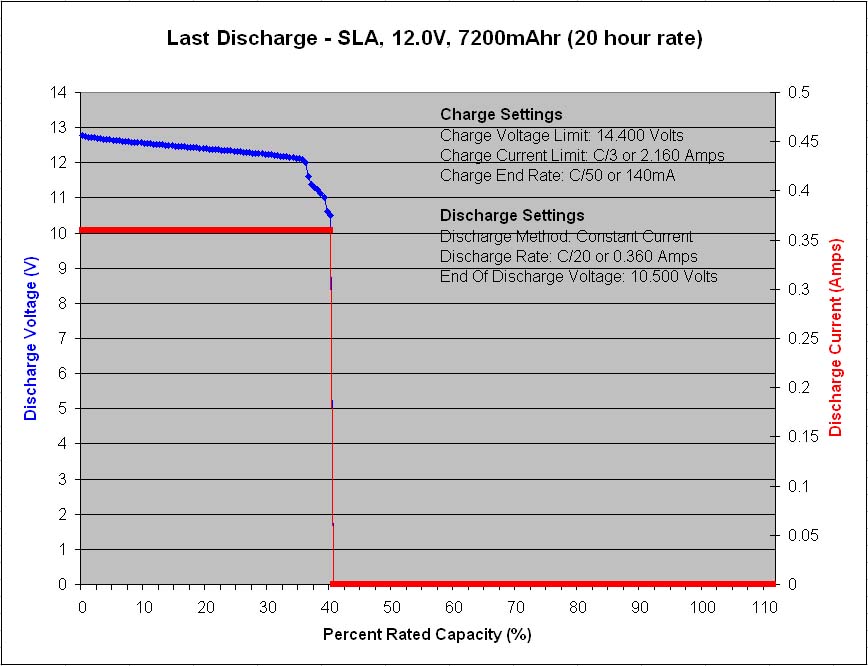
Figure 3 – Final capacity test at C/20 rate
 A final discharge test was performed at the C/20 rate once again to see how the battery would perform at the lower discharge current and its tested capacity immediately bounced back to 40% of its rated capacity.
These life cycle test results are interesting with a couple of things worth noting. The first is the rapid capacity decline during the first 250 cycles followed by the slower capacity decline for the remaining 750 cycles. It seems as though there are two different wear mechanisms at work simultaneously, one that deteriorates the battery capacity very rapidly and then exhausts itself, and a second that deteriorates the battery capacity very slowly but endures.
The second item worth noting is the sudden voltage drop near the end of discharge in figure 3, with a small plateau, followed by another quick voltage drop to terminate the discharge. These quick voltage drops are due to lower capacity cells losing their voltage rapidly, unable to maintain their load current at voltage. This indicates a probable cell imbalance issue whereby the lowest capacity cells are not getting the opportunity to fully recharge during the charge portions of the cycling, and in turn are limited in their discharge capacity during the discharge portions of the cycling. A cell imbalance condition may be effected by the heavy cycling demand of the life cycle testing itself which leaves little time for float charging at the end of each charge portion that would normally help to balance the cells connected in series. A cell imbalance problem is typically a self-perpetuating vicious circle and from looking at the discharge voltage profile results during the first 250 cycles (not shown in this post), it can be seen that a rapid voltage drop near the end of each discharge portion starts to appear gradually during the first 250 cycles, so this may in fact be the real reason for the rapid capacity loss during the first 250 cycles, a cell imbalance problem, and not a two stage wear mechanism as was first proposed above.
A possible way to determine if a cell imbalance issue is in fact the main problem causing the rapid capacity loss in the first 250 cycles would be to repeat the life cycle testing once again, but in the second attempt try setting the test configuration to using a higher charge voltage during the charge portions in order to force more capacity into the series connected cells with the intent of providing an increased amount of overcharge to the healthier cells while likewise providing a more complete charge to the lower capacity cells in order to maximize the ability of the cells to work together and prevent a cell imbalance problem from self perpetuating toward rapid capacity loss.
The charge voltage maximum used for the testing in this example was 14.400 Volts and the recommended charge voltage from Panasonic for cyclic applications with this battery is 14.5-14.9 Volts, so in a future life cycle testing I would try using the highest recommended charge voltage at 14.900 Volts to see what improvements can be achieved.